
![]()
ERPS: POGO Mk 0
| The Bay Area's Non-profit Liquid Fuel Rocket Engine Design and Test Team |
[an error occurred while processing this directive]
The vehicle has two main sections, an Upper Section (containing the RCS, Pressuant and Vehicle Apex systems) and a Lower Section (containing the Propellant Tank, plumbing, Base Plate and Landing Legs). The Upper slips over the Lower and is bolted in place to form the full vehicle.
Below are a number of photos of the Mk 0 and brief descriptions of what you're looking at. Certain parts have been removed to protect proprietary technology (such as the engines and RCS systems). Sorry. 8-)
| Image | Comment | Photo By |
|---|---|---|
|
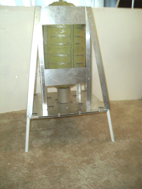
Propellent Tank Lower section, showing the propellant tank support frame. vehicle frame, legs and plumbing spacer. |
mjw |
|
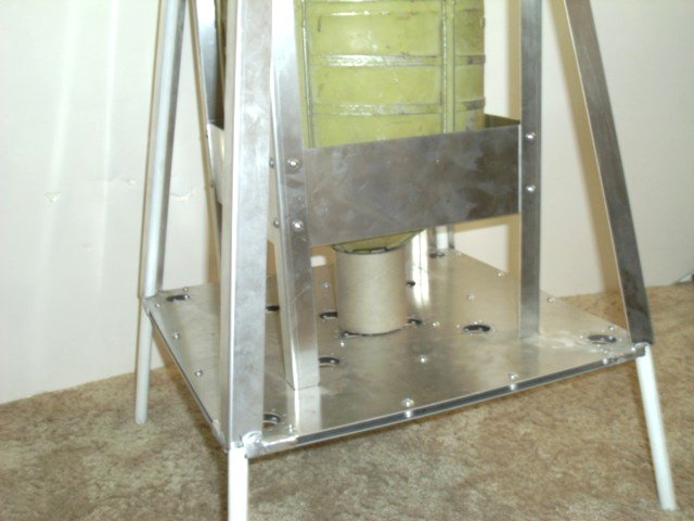
Base Plate Lower section showing the base plate, the legs, the vehicle sframe and the propellant tank support frame, with tank. |
mjw |

|
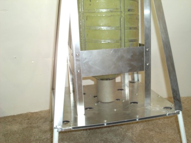
Attach Points Closer view of the base plate attachments to the propellent tand support frame, including the plumbing spacer (cardboard tube). |
mjw |
|
Upper Section The upper section, including vehicle frame, pressuraant tank, pressurant support frame and RCS platform with RCS engines and valves removed. |
mjw |
|
Pressurant Tank Closer view of the Pressurant Tank and it's support frame. The RCS Platform is the flat plate on top of the tank. |
mjw |
|
Attach Points A closer look at the Upper/Lower section attach points, The angled vehicle frame legs slide over, and are then bolted to, the Lower Section Vehicle Frame. |
mjw |
|
RCS Bay Closer look at the RCS bay and vehicle frame apex, with the RCS equipment removed. |
mjw |
|
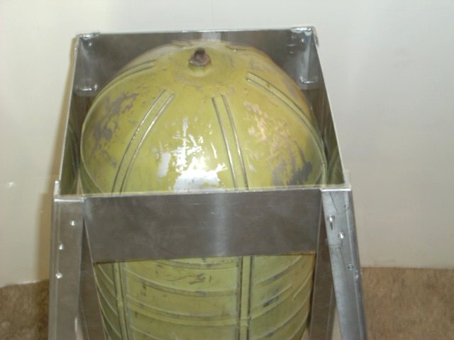
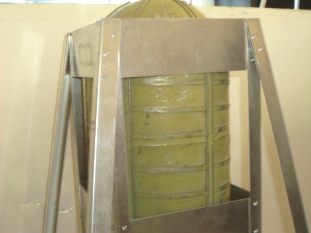
Lower Attach Point Close look at the Lower Section Vehicle Frame attach points, and the top part of the Propellant Tank. The Upper Section slides onto the Lower and is bolted in place. |
mjw |
|
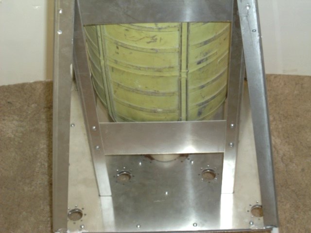
Base Plate/Tank Support Closer look at the interface between the base plate and the propellant tank support frame. The outer engine attach circles are visible, as are the mid circles under the tank. |
mjw |
|
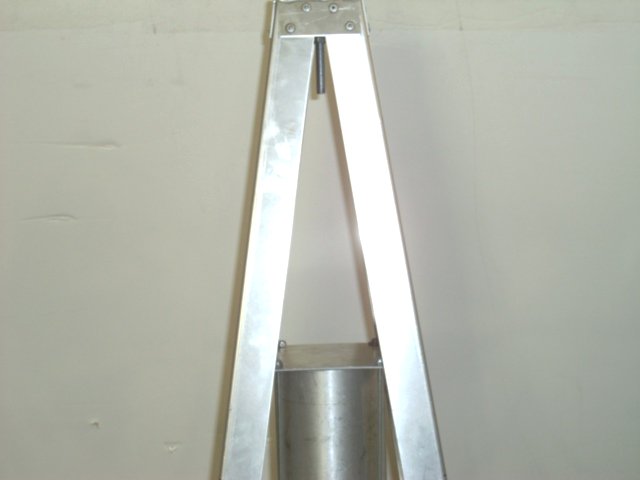
Vehicle Frame/Tank Support A closer look at the top of the Lower Section, showing the interface between the frame, the tank support and the tank. The Upper Section Bolt Holes are also visible. |
mjw |
|
Engine Attach Circles A closer look at the base place showing the engine attachment circles. Near the plumbing spacer are the Inner Engine Attach Circles, then the Miid Attach Circles, the Propellant Tank Support Frame and then the Outer Engine Attach Circles. |
mjw |
|
Engine Circles A slightly rotated view to more clearly see the three sets of 4 Attach Circles. |
mjw |
|
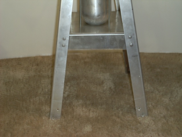
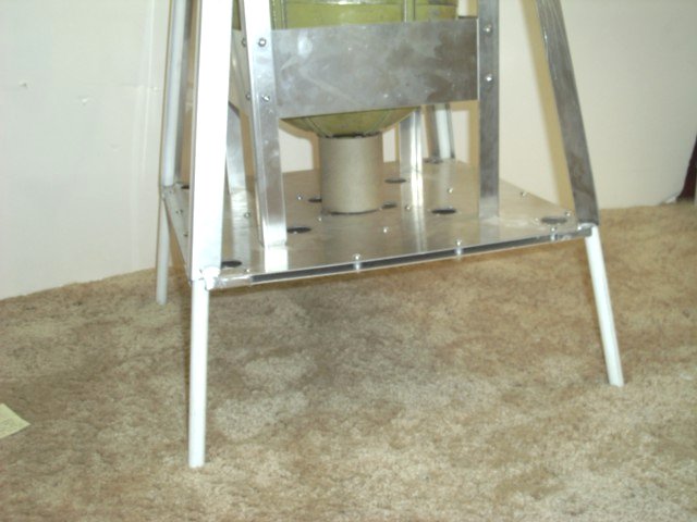
Vehicle Legs A closer view of the Vehicle Frame and Landing Legs, showing them extending down from the Vehicle Frame. |
mjw |
|
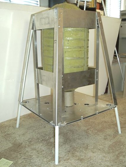
Lower Section All up shot of the Lower Section |
mjw |
|
Perspective L perspective shot of the Lower section showing the frame, legs, base plate, engine circles, plumbing spacer, propellant tank and it's support frame. |
mjw |
![]()
Copyright ©
2007
Last updated:
16:53 on 28 May 2007
Web services provided by: Wallis
International Networking Services